Introduction
This article is partly based around a piece written for the old website (objectivesounds.co.uk) that was originally put online in 2015. In the interim many people e-mailed in, having read the article and built a simplified version of the improved circuit detailed in the 5th section. The original article described these circuits in a more abstract form and without certain components such as input decoupling which at the time were not shown for simplicity, and it was assumed would added by the constructor if necessary.
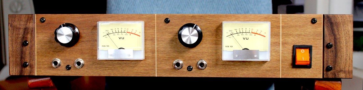
Figure 1. VU meter unit built by Bevan Galbraith
I was lucky enough to receive several very beautiful pictures of readers' builds, such as the one shown in Figure 1. Judging by the general feedback received in the 4 years that the article was available, most people who built the improved circuit built it as a stand-alone unit, or in conjunction with passive circuitry as in Figure 1, a guitar re-amp unit. It became clear that a lot of people were having difficulty with getting the circuitry to work as it was not apparent that these omitted elements may have been necessary. Due to this, the schematics in this article have been updated to include input decoupling, a brief description of a very simple power supply to satisfy the circuit's modest needs, and a more practical focus to ensure that they will be able to work as-is with any line level source.
There's nothing quite like sitting back and admiring the view of a warmly lit pair of elegant analogue VU meters responding in perfect synchronisation to whatever you're listening to. True, there are many great digital level indicators, even some that attempt to emulate a moving coil meter on-screen. But these can only be used for PC audio, and aesthetics wise, in the opinion of the author, don't even come close to the real thing.
VU, or Volume Unit, meters are a way of measuring the level of an audio signal. They measure the an average of the signal they are presented with, not the peak level or the RMS level, which is displayed in decibels in respect to a preset level. VU meters have historically been used where careful level control is required in order to optimise signal levels to fit within a limited dynamic range, and hence can be seen in some form or another on all but the very cheapest tape recorders. Due to their average level measurement, they are much better suited to maximum level monitoring for tape recording, where distortion increases gradually as the audio level reaches and passes full scale. Briefly exceeding full scale with some mild non-linear peak compression may not yield any noticeable impairment. Digital audio recording, which is for all intents and purposes distortion free until the level exceeds the absolute maximum and gross distortion in the form of hard clipping is not well suited for absolute level monitoring as some peaky waveforms, while showing a moderate reading on a VU meter may be easily clipping to the point of audible distortion. This has lead to VU meters earning the moniker of 'virtually useless meter' in these settings.
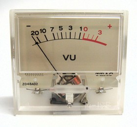
Figure 2. Classic moving-coil VU meter from a Teac cassette deck
Figure 2 shows a cheap and mass-produced style of VU meter commonly found on consumer units in the days of tape recording, dating back to the late 1970s or early 1980s. Even today, analogue VU have some very useful applications for professional and non-professional use alike. They are invaluable for monitoring average levels and give a good indication of the perceived loudness of the source they are connected to. In professional line level settings where headroom in excess of 10V will be present, the point of peak clipping may well be some 18dB or so above 0VU with typical program material, so they are still an excellent means to set levels analogue line levels by.
In a consumer listening environment, VU metes can be very effectively deployed to show how 'loud' CDs and other digital audio sources have been mastered when connected to a CD player standard audio interface. Fortuitously, a full scale output from the vast majority DACs is around 2V RMS. A VU meter configured for professional line level reads 0dB when the input voltage has an average of 1.125V meaning that a reading of +4dB will be shown when a sine wave of 2V RMS is present, the maximum undistorted level. The same can be done with phono inputs, once past a pre-amplifier with a suitable gain of 37-40dB, and the differences in levels between certain labels and formats may surprise you.
There is also purely the aesthetic function of having them on a unit, a perfectly valid reason, as long as the meter itself does not degrade audio quality in some of the ways that will be made apparent further on. After all, the end goal of HiFi is enjoyment!
The VU meter standard
VU meters have been around for over 75 years now, since Bell Labs and various broadcasting companies in the United States standardised a method of measuring average levels in telephone lines and other signal carrying cables. The standard defined by the ANSI requires fairly strict tolerances in terms of the mechanical aspects of the moving coil meter itself, not withstanding the electrical components. In order to provide any meaningful indication of an AC signal a rectifier must be used to generate a proportional DC voltage across the meter coil. This rectifier consists of fairly esoteric low voltage drop elements so as not to decrease the meter's sensitivity to small signals. All this makes true VU meters rather costly. Even second hand meters can cost upwards of £70 per unit. For a new unit, expect to pay perhaps three times this price. The basic requirements of the standard are listed below.
- The rectifier should be a low forward voltage full-wave germanium, or now obsolete copper oxide, type so as not to adversely affect the sensitivity of the meter. This is usually included inside of the meter itself.
- The meter's scale should be adjusted to compensate to accommodate the forward voltage of the rectifier.
- The meter should display 0dB when presented with a sine wave that has an RMS voltage of either 1.228V (+4dBu) for professional line level or 300mV (-10dBV) for consumer line level.
- The frequency response of the meter should be down no more than 0.5dB at 25Hz and 25kHz.
- The meter should take 300ms to reach 99% of it's travel in any direction.
- The meter should undershoot by no less than 1% and overshoot no more than 1.5%
- The meter should read 0VU when a current of 200μA flows through the coil.
- The meter should present a load impedance of 7.5kΩ to the drive circuitry at 0VU. In order to achieve this, it is common practice to connect a 3.6kΩ resistor between the source and the rectifier.
Due to the very tight mechanical tolerances required to do so, it should be apparent that these targets will not be met in the vast majority of domestic (and sometimes even professional) cases. You can rest assured that any VU meters on domestic recording equipment such as cassette and reel to reel recorders will not conform to the specifications listed above. This isn't too great a worry as all that we really want is to see a reading of 0VU when the signal reaches a level where distortion will be likely and does so without any significant overshoot, insensitivity to low levels, or a delay of over 500ms or so.
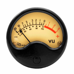
Figure 3. Sifam AL20 VU meter
Having said that, it's always good to try and get as close to the real thing as possible when working with lower cost non-standard meters. In many cases meters that fall even just slightly shy of the standard, but are still excellent, will be priced a factor of two lower than ones that meet it. Such is the meter shown in Figure 3 which costs £50: a most attestably well constructed piece of work, with its snappy movement, black phenolic housing and solid glass window. Further reading will show that there are even a couple of improvements to be obtained by using non-standard active drive circuitry, with low end sensitivity being a major one. A brief allusion to this problem can be seen on the face of the meter in Figure 3; the distance between the -20(dB) threshold and 0% is far smaller than the tenth of the scale that it should be to 100%. When a drive signal of 10% full scale (-20dB) is applied, the needle will only move maybe 2% of full scale.
ANSI VU meter circuit
Before having a look at more common active circuitry, it’s helpful to cast a brief glance at the standard VU meter circuit as it has appeared in professional audio equipment over the ages. In most cases the entire circuit is enclosed within the meter housing enabling the meter to be connected directly to the signal to be monitored. It’s quite a simple circuit, but some analysis here will be useful in laying out some of the basic operational fundamentals and traps of circuitry to be described later on.
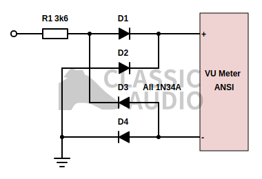
Figure 4. Basic ANSI VU meter schematic
Figure 4 shows the circuitry that appears in most professional VU meter circuits that meet the ANSI standard. R1 provides the necessary 3.6kΩ inline resistance in order to reduce loading on the drive source and supply the correct amount of current to allow the meter to work accurately. This current is then full-wave rectified by D1, D2, D3 and D4 in the usual arrangement and then fed into the meter, which can only respond to DC current flowing through it. The diodes that make up the rectifier must have a low forward voltage or the low end sensitivity of the meter will suffer greatly, so they are germanium types (or in the case of some very old meters copper oxide rectifiers). If they were to be standard silicon diodes such as the ubiquitous and very low cost 1N4148 types, then the meter will be quite insensitive to peak voltages under 1.2V or so, as the drive signal will have to overcome the forward voltage of two of these diodes before any current can actually make it through to the meter movement. Unfortunately germanium diodes are not the cheapest of components, or the most durable, being particularly susceptible to heat damage during soldering. It may now be possible to use Schottky diodes in such arrangements as they typically have a much lower forward voltage than standard silicon diodes, but in the estimation of the author, they will most likely give a poorer performance here than germanium devices.
The meter itself has no electrical damping, and in VU meters that are made to conform to the ANSI standard great care is taken to ensure that the mechanical ballistics of the meter's moving assembly will meet the specifications defined in the previous section of this article when used in conjunction with the arrangement in Figure 4.
It is important that the meter is driven from a very low impedance source, otherwise the highly non-linear load that the rectifier presents to the driving circuitry will result in a high level of distortion being added to the audio signal. From personal experience the author can attest that even with a comparatively low line level driving impedance of only 300Ω, audible distortion was present when the meter input was monitored with this configuration. It can therefore be concluded that in order to safely use this simple passive circuit successfully, it must be driven directly from an op-amp output, which will typically be less than 1Ω, if the addition of significant distortion is to be avoided. Typical line impedances will seldom be below 70Ω which makes this unhappy scenario highly likely in practice. In almost all cases it is good practice to drive the meter from a separate output or through a suitable buffer amplifier to completely eliminate this problem, but there is still another distortion trap hiding in the meters ground current which will also be highly distorted. The meter must be grounded to a separate ground, typically a power ground, path than the audio signal otherwise this nonlinear current could potentially generate a small voltage in the ground path that could still add enough distortion to seriously compromise overall non-linearity to the tune of up to 0.1%.
A historic non-standard VU meter
Having taken into account the great cost of producing a meter that meets the standard defined by the ANSI and various complementary standards to the same effect elsewhere in the world, it should be clear that due to cost limitations a great many of the VU meters found in consumer, and even some professional equipment, will fall short these specifications in some way or another. In practice this does not in fact matter much, and useable examples of non-standard VU meters that break the rules in some way can be found in a plethora of consumer units.
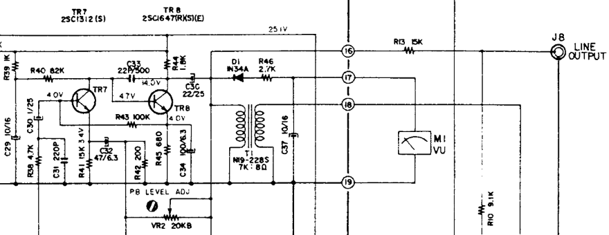
Figure 5. AKAI 4000DS VU meter circuitry
Figure 5 shows just such an example, taken from the service manual of the ever-more-sought-after - for reasons that seem not to have very much to do with high fidelity recording and playback in the 21st century - Akai 4000DS reel to reel tape deck. It’s a fairly standard topology from the ‘golden-era’ of relatively large analogue VU meters on consumer with a few interesting workarounds; historical features that make it worth examining here.
It is clear at a first glance that the circuit does not use full-wave rectification, saving a total of three then even more expensive germanium parts per channel. Instead D1, a lone 1N34 germanium diode is used to provide rectification of the audio output, which is delivered to the meter through R46, with electrolytic capacitor C37 providing electrical damping to the meter which would otherwise probably exhibit overshoot, being manufactured to a cost and not a specification. At first glance it is observable that the rectifier will generate a negative DC current with respect to ground. The meter movement is therefore connected with its positive terminal to ground. There is a good reason for choosing seemingly strange positioning as the driving amplifier more able to sink current through the collector of TR8, than source it effectively through R44, thus a negative current must flow through the meter with respect to ground, and D1 points into the driver amplifier, rather than away from it.
As the meter is AC coupled through the same path as the line output, via C30, an equivalent positive DC current must flow somewhere from the negative end of C30 to ground. At first it would seem that this would have to generate a quite substantial positive offset on the line output, but another trick is employed here to reduce this ill-effect to an acceptable level. The headphone output transformer T1, necessary to couple the once ubiquitous 8Ω low impedance headphone output to the line output amplifier, allows a solution to be found. The windings on the high impedance side, connected across the same path as the VU meter rectifier circuitry, present a low enough DC resistance of around 200Ω, to prevent DC offsets and transients high enough to cause serious upset from accumulating across the line output. If this component was not present, then the VU meter rectifier would have to coupled through a separate decoupling network with a fairly low value resistor on the lower arm, passing on a much increased load to the already rather stressed line-headphone-meter amplifier.
The driving amplifier itself somewhat satisfies the requirement of having a low output impedance, as it uses a high degree of negative feedback via VR2. The classic double NPN configuration that found its way in to most audio circuitry of this era is used, with negative feedback being delivered to the emitter of TR7 through C32. The output impedance is determined by capacitor C30 as frequency decreases, and hence the distortion generated by the rectifier, will rise quiet significantly as frequency reduces, easily degrading the distortion to over 1% or so approaching 50Hz. The spec for the whole unit states that distortion is 1.5% at full level, so it is most likely that the distortion limitations of the tape itself would have at least masked the worst of the meter distortion in the more crucial mid-range. This low frequency distortion could be mitigated by increasing the value of C30, which is already a factor of five too small to modern eyes, but would bring a cost penalty in addition to potential problems with greater turn on transients. When the unit is powered up, the positive end shoots up to approximately half the supply voltage; more capacitance means more current flow in this condition. Adding an additional muting circuit and output relay would have increased costs to an unacceptable level, and usually single supply circuits like this one were carefully designed so as to generate an acceptably low level of transient noise at switch-on, typically by adjusting various RC time constants upstream of the output through trial and error in the lab.
Lastly, the line output itself is fed through an L-pad attenuation network consisting of R13 and R10, reducing the level by some 8.5dB and adding 5.66kΩ of output impedance onto the line output, which is awfully high in retrospect. The high resistor values were most likely chosen to avoid putting another heavy load on the busy line amplifier. It’s most likely that the designers were aiming for a 10dB of reduction in level when the unit was connected to the input of the average integrated amplifier of the day which would be expecting an input level of 100mV or so, again very low in comparison to the offerings of today. The reason for this quite severe reduction in level is twofold. Firstly it allows the line amplifier to develop enough voltage at its output to sufficiently drive the meter, which is already only half as sensitive as it might otherwise be due to the half wave rectification, and break through the forward voltage of D1. Secondly, the line amplifier must also drive the headphone transformer with enough level to generate an adequately ear-splitting sound in the headphones when they are plugged in, the expectation being that they will be pressed into service when otherwise antisocial amounts of noise are required.
Although Figure 5 is quite unusual in the amount of function it derives from a seemingly limited number of components, this sort of topological trickery was quite common, with many different needs being served with the meter itself taking second place as somewhat of an after-thought. In most cases, these meters gave a less than stellar performance with a noticeably slow response time, and movement that seemed to be following some form of counterpoint of its own volition to the programme material itself, but were good enough to set recording level in low cost tape recorders with already uninspiring specifications. For this reason, such circuits are best repudiated to be left in the past, and not copied into the future, where components of greater flexibility such as op-amps are ready to step up to task and yield far more satisfying results.
Improved VU meter driver circuit
The circuits described thus far have shown themselves to exhibit two major problems, that should be addressed if an excellent performance is to be obtained without using expensive parts. The first is the problem of drive, with the non-linear effect of the rectifier potentially harming overall linearity, either directly through loading, or indirectly via ground current. Secondly there is the issue of diode forward voltage, which degrades the low end sensitivity of the meter, producing a dead zone for peak signal levels 20dB or so below full scale.
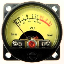
Figure 6. 500μA VU meter seen on many online marketplaces
The improved drive circuitry described in this section was originally designed for use with Figure 6, a comparatively current-hungry low cost meter, mass produced in Taiwan, and made available on several direct selling online sites. It's certainly not a standard meter type, but works very well as its diminutive size, and therefore low mass moving assembly, is pleasingly sprightly and responsive when driven correctly, in stark contrast with the aforementioned historic example.
By calling in some active circuitry in an appropriate form, we can do away with all of these infelicities, with a single stage design, while also adding some extra functionality that will go a long way in the real world. The active device of choice here will be the TL072 op-amp, although its sister devices such as the TL052, TL062, and TL082 will suffice just as well. Although this device is much maligned for its inferior noise and distortion performance, high-level common mode misbehaviour, and load driving ability, none of these weaknesses are of particular consequence for the following application. This low cost and readily available part has been available for some 40 years now and can be reasonably foreseen to be still available in the next 40 years. This is much unlike the very latest-and-greatest audio op-amps that seem to explode onto the market every year, only to implode several years later.
The TL072 has high impedance JFET inputs that will not draw any significant input bias currents compared to BJT input devices, permitting a complementary high impedance input coupling network that will present a most leisurable loading to whatever audio source we might chose to connect it with. The corresponding lack of appreciable input current noise due to the JFET input will also prevent any possibility of noise being induced onto a high impedance source. A slew rate of 20V/μs is also most suitable for purpose, fast enough to quickly punch through the rectifier when required, but not so high as to potentially cause problems with stability in a conventional layout, or a one-off type construction of strip-board. Finally, the TL072 and her sisters of minor variation issue attractively low demands when it comes to quiescent power - at a maximum of 2.5mA per amplifier, typically 1.4mA, along with a minimum power supply rejection ratio of 70dB, typically 100dB, which allows a very simple and low cost power supply to be used, as will be described further on.
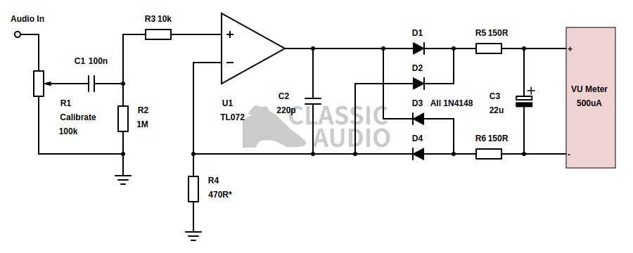
Figure 7. Improved active VU meter driver circuit
Figure 7 shows the improved driver circuit using our op-amp of choice with, a split supply arrangement. The power rails are not shown here for simplicity, but a 100nF capacitor must be connected across the op-amps power pins to avoid any potential instability caused by stray inductance. It is not a complicated circuit, consisting of 1 potentiometer, 5 resistors, 3 capacitors and of course the op-amp and VU meter itself. It is assumed that 2 identical channels will be built out of each of the two individual op-amps contained within the TL072 IC.
The audio input is referenced to the circuit ground and can range from 235mV RMS, to more than 10V RMS, with the sensitivity of the circuit being continuously adjustable between these two points via potentiometer R1, which may be a small set-and-forget preset type calibrated to any level within this range by the constructor, or possibly a panel mounted device to allow external control. The input impedance seen at the audio input by the source will be a very undemanding load of 91kΩ at the most sensitive setting and approach 100kΩ as the sensitivity is decreased to a point of total deafness when the potentiometer wiper touches ground. This sort of high impedance is suitable for practically any line level audio source that can be imagined. A potentiometer with a value of less than 100kΩ, may be used with 10kΩ being the lower limit for most line level sources, although some vintage sources such as that in Figure 5 will perceptibly remonstrate by exhibiting significant loss in level and possibly increased non-linearity. Therefore, the lowest advisable value to be used in the estimation of the author should be 20kΩ as this would still allow additional loading from another input, from say a pre-amplifier, to be connected to the source without soliciting any undue grief.
The level adjusted source at the potentiometer wiper then finds itself DC decoupled through C1 and onto R2. As already mentioned, the TL072 has a high impedance JFET input that draws practically zero input bias current, and can be relied on not to generate a significant DC offset across the 1MΩ of resistance that R2 places at DC between the non-inverting input and ground. This high value allows C1 to be made correspondingly small, at 100nF - usefully the same value as the not visible op-amp supply rail decoupling capacitor, without the risk of premature low frequency roll-off, which would produce an insensitivity to lower frequencies still within the range of hearing. This lower value necessitates a non polar capacitor with a polyester or possibly ceramic dielectric, resulting in an immunity to quite diabolical levels of DC offset on the audio input, greater than even the worst expected from the most ill conceived of equipment put into possession of the leakiest electrolytic output coupling capacitors. R3 performs the function of a crude RF filter in connection with the JFET input capacitance of the TL072, helpfully isolates this slightly non-linear capacitance from the source at maximum sensitivity, and finally affords robust input over voltage protection in tandem with the input clamp located inside the TL072. In high fidelity audio design, a series resistance greater than 2kΩ on the input of a TL072 is to be avoided due to the increased non-linear effect of the input capacitance, which varies with voltage, but in this instance it is of no consequence as it does not skew the average rectified measurement by any real degree.
The op-amp U1, then follows the AC voltage present on the non-inverting input onto R4, through the AC side of a full-wave meter current rectifier consisting of D1, D2, D3 and D4. Connected in parallel with the rectifier is C2, whose purpose is to make certain that there is no high frequency instability or an excessively non-linear high frequency reference received across R4 as the op-amps open loop gain slowly drops off at high frequency, its value being carefully chosen so as not to allow so much high frequency bypass that the sensitivity of the meter is curtailed at the top of the audio band. The rectifier diodes are all inexpensive and easily acquired 1N4148 silicon types and with a heretofore undesirable forward voltage of 0.65V. This is no problem as, the rectifier is driven by what is essentially a constant current source, which makes the forward voltage irrelevant. The op-amp will almost instantly punch through the combined rectifier forward voltage near instantaneously to deliver the current needed to replicate its input voltage across R4. The meter can now respond to low level signals, far below the threshold voltage of the rectifier diodes in the ANSI circuit of Figure 4, while simultaneously doing away with the expensive and fragile germanium diodes. Only the op-amps' DC offset threatens low end sensitivity, typically a factor of 100 less than the combined germanium diode threshold voltage in the ANSI circuit does.
The driver circuit's ground current is now perfectly clean, a linear function of input voltage, as should be the case when the input voltage is replicated across R4, a device linear by definition, by U1. When 235mV is applied across R4, 500μA flows through the meter, pulling the needle to the maximum end of the scale. As the common mode voltage on the op-amps inputs will not exceed more than about 1V peak during normal use, undesirable common mode foibles of the TL072, such as the non-linear input capacitance are not able to rear their heads above the parapet of negligibility to get a few painful shots in. One particularly aggravating effect that comes into play as the common mode voltage approaches the negative supply rail of a TL072, is that the output swings up all the way to the positive supply rail - a truly awful sound to those who have heard it.
A few more components are necessary to make the circuit behave itself outside of the theoretical. Resistors R5 and R6 give the op-amp output enough isolation from any stray capacitance that might exist in the wiring between the meter and the drive circuit, to prevent stability margins from evaporating into acrid fumes of oscillation. These resistors also help to limit the distorted high frequency transients from the rectifier, whose current is now undistorted, but whose differential voltage output most certainly is not, that might undesirably capacitively couple themselves onto any nearby cabling that may or may not be carrying an, up till then uncontaminated, audio signal. It is highly recommended that if more than a few centimetres of wiring is to be seen in place between the meter and the drive circuit, that it be in the form of a twisted pair, which will almost entirely eliminate this possibility. Under no circumstances should the negative end of the meter by connected to ground. Finally C3 is included to damp the movement of the low cost meter so that it does not overshoot and give stronger reading than is warranted by the programme material.
The schematic in Figure 7 is designed to run on a split supply of anywhere from ±6V to ±17V, close to a factor of three - it is not fussy at all. A split supply arrangement is almost always far better than a single supply one where the op-amp and active circuitry is powered through a positive rail, with the negative supply currents, inevitably far less than linear for all but the most carefully designed discrete class A circuitry, flowing through the same ground as the audio. Unless more diligence than the author has repeatedly observed out in the wild is taken, these non-linear currents will stimulate corresponding non-linear voltages in the parasitic resistance of the ground path, when then aggregate themselves with the otherwise undistorted audio signal. All of a sudden distortion is a factor of 10+ higher than it should be. One particular small manufacturer here in Britain, who shall remain anonymous is a perfect example of this ill effect in practice. Several of their units exhibit rated THD up to 2000ppm. The author can attest through experience that op-amps contained in said units are capable of at least 10 times greater linearity with a more sensible supply topology. Said manufacturer obdurately refuses to accept that there is anything at all amiss, complaining vociferously through a series of convoluted and almost indecipherable statements to all who will listen, that he is maliciously persecuted by anyone who mentions this to anyone else, in any place, and at any time - such statements being comparable to mortal wounding!
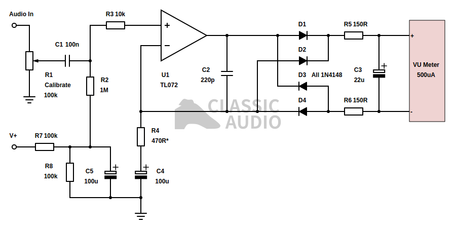
Figure 8. Single supply VU meter driver circuit
Having heaped an elephantine pile of admonishment onto the single supply method, it is worth saying that there are some cases where only a single supply is available and it is most infeasible to even attempt deriving a split supply to power the circuitry of Figure 7. For this reason, the circuit shown in Figure 8 is offered to demonstrate how it can be done. Using a split supply requires the inclusion of an extra two resistors and capacitors. R7 and R8 generate half the supply voltage as bias, with C5 AC decoupling any supply noise or ripple that might be perched restlessly on the positive supply rail. It is expedient to omit R7, R8 and C5 from the second channel, if two channels are being built, and instead derive the bias from the positive end of C5 from the first. As C5 charges when power is applied, the bias level lifts up slowly for the benefit of the meter when power is applied, rather than savagely assaulting it with half the supply voltage. C4 AC couples the bottom end of R4 to ground: it cannot be directly connected as the full bias voltage, half the supply rail, would then straddle the rectifier and meter assembly, sending the needle shooting off to the right and potentially damaging the coil.
The supply voltage can be anywhere between +12V and +30V and all electrolytic capacitors should be rated at or above the supply voltage. No more than 10mA of current will be drawn during normal operation, and the circuit is very tolerant of supply rail noise. A volt or maybe more of ripple, noise, or any other unpleasantness on the supply rail will not affect performance. The high degree of smoothing effected by C5, in connection with the high resistance of R2 affirms that no power supply noise can couple onto the audio source and inject electrical detritus. As with Figure 7, an op-amp supply rail capacitor of 100nF must be connected across the power pins, or instability will eventuate. If it is not evident at this point, the op-amp positive supply pin should be connected to V+ and the negative pin connected to ground (0V).
*The value of R4 was calculated to admit a rated meter current of 500μA, +25% for meter calibration, in conjuction with a consumer line level voltage of 300mV (-10dBV). If a meter requiring less than 500μA for a full reading is to be used, then the value of R4 can be increased in a manner inversely proportional to the rated meter current relative to 500μA. It is important that this is done, as it will prevent op-amp offset voltage from deleteriously affecting the low end sensitivity of more sensitive meters. For example; a meter with a rated current of 200μA, 2.5 times smaller, would warrant changing R4 to 1.2kΩ. A 100μA meter, would be best suited to an R4 value of 2.2kΩ, a 250μA part 1kΩ, and so on and so forth...
Adding peak detection
The VU meter's unofficial appellation of ‘virtually useless meter’ is not entirely unearned. While VU meters do give excellent indications of general loudness and average levels, they are quite unable to reveal anything more than an implied approximation of peak level, which may be significantly higher than the average level might imply either due to transient peaks or highly asymmetrical waveforms such as human speech. Consequently it is quite useful to include a peak indicator in the form of an LED that will illuminate once the peak level reaches 3dB over 0VU; the same peak level present on a sine wave at 0VU. Since publishing the article, various discussions on adding peak detection to Figure 7 have not led to any satisfactory conclusion. Being presented with the LED output peak detection circuits available elsewhere on the web, for use as add-ons to the circuitry described in the article, that either offer very crude unipolar detection (only sensitive to the AC waveform in one direction), insensitivity to brief peaks, non-linear loading of the line that promises severe distortion, or complete atrocities that just won’t work at all, the author has taken it upon himself to contrive a complete VU meter drive circuit with high quality bipolar peak detection.
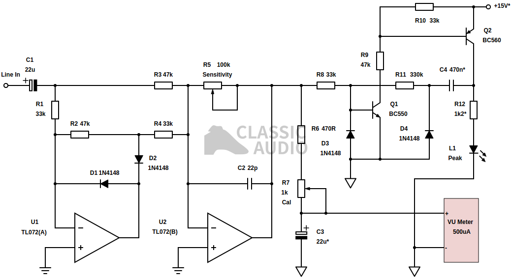
Figure 9. VU meter driver circuit with bipolar peak detection
Figure 9 exhibits the product of an evening in the workshop languorously fiddling with some common parts on the test bench. The topology is a necessary departure from the current driven bridge rectifier arrangement of Figure 7 as a consequence of the need for a rectified DC voltage relative to ground for the purposes of peak detection. Audio comes in through coupling capacitor C1 and is full-wave precision rectified to a positive DC voltage by U1 and U2, whose gain is adjustable via R5. U2 drives the VU meter through R6 and calibration trimmer R7, with C3 performing a little smoothing and meter damping. NPN transistor Q1 performs peak detection via its base threshold voltage on the rectified output of U2 through current limiting resistor R8, switching on PNP transistor Q2 once the base voltage exceeds 550mV or so. Q2 drives the peak indicator LED L1 through current limiting resistor R12, and also applies positive feedback towards Q1 through C4 and R11, so that the detector switches hard on for long enough to be visible once the peak threshold is met.
The precision rectifier is a fairly standard arrangement of the kind that is frequently shown as an example of its kind on electronics websites and text books. A slight quirk is that the values of the input resistor of the half-wave rectifier stage, R1, and its feed into the summing amplifier, R4, are selected so as to double the half-wave rectifier's current into the summing stage relative to the non-rectified input, through R3, by making the product of their values double to the square of summing input resistor R3. This is a little different to having to select E24 values to double the current, or pairing up resistors to halve or double their values, either by series or parallel arrangements, and is a useful little trick that makes the circuit a little more ergonomic to build. As R1 and R3 feed into virtual earth points, the input impedance is set by R1 and R3 in parallel to present a fairly innocuous 19.4kΩ to the whatever the metering circuit is connected, which should be unburden-some enough for most unbalanced line circuitry, and no problem at all for the balanced receiver to be described in the next section. The gain of the rectifier is continuously variable from zero to 2.12 which allows a peak input voltage of as low as 260mV to be calibrated to trip the peak detector. C2 ensures that inverting stage U2 is stable at HF while the parasitic capacitance of D1 does the same for U1.
VU meter drive is quite unremarkable, simply consisting of a variable series resistance in the form of R6 and R7. R6 is included to make the circuit foolproof and prevent the possibility of damage to the meter movement if R7 is shorted out during calibration. If a meter with a current rating deviating from that shown in the schematic is put into service, then R6 and R7 will have to be adjusted to the inverse of the difference. C3 performs damping of the meter movement and shunts away most of the HF nastiness that might couple from the meter movement wiring onto an otherwise distortion free audio connection. Note that a different ground symbol is used to indicate that the ground current will be quite polluted with very high levels of high order harmonics as a result of the full-wave rectification. It is unavoidable with this topology that the ground current will be significantly distorted and therefore the meter ground should be connected much further downstream towards the power supply circuitry, preferably straight to the power supply 0V rail, and not be shared with any audio circuitry. It is otherwise practical to drive VU meters from precision rectifiers as shown, and use a capacitor in the range of 1μF in place of C2 to smooth out the harmonics in the feedback loop of the precision rectifier summing amplifier, and therefore make the ground current clean enough to allow a little more flexibility with layout; doing so here will make the peak detection quite uselessly insensitive to transients.
Far too many peak indication circuits listed elsewhere on the web only light up the LED for the duration of the peak, which may only exist for 10μ in many cases and will be far to brief to be visible unless the users gaze is permanently fixed on the indicator LED with no natural light present. Some require the peak to charge a capacitor to hold the peak for long enough to be visible, degrading the sensitivity to brief transients that may not exist for long enough to charge the sampling cap. The peak detector circuitry described in Figure 9 uses positive feedback via timing capacitor C4 so that once the base voltage of Q1 has been breeched for even the shortest period of time, the indicator LED will stay on for at least as long as it takes for C4 to charge up through R11 and Q1; about 250ms with the supply voltage of ±15V shown. Clamping diode D4 allows C4 to discharge through the much lower resistance of R12 and the indicator LED so that the circuit is ready for action again within 2ms of either the peak threshold voltage disappearing from the detector's input, or C4 completing its charge cycle; whichever occurs later.
High current gain BC550 and BC560 general purpose transistors are prescribed for Q1 and Q2, but they can be any general purpose small bipolar transistors that the constructor has on hand, the parts specified being those in the closest reach of the author. Diode D3 clamps the input of Q1 to prevent it from possible damage should U2's output assume a negative voltage of more than -5V; rather unlikely and to the author's knowledge only realistic with a severe positive input over-voltage on the line in, or perhaps some curious behaviour when powering up and down, however unlikely; it is still included as it is an inexpensive, easily fitted part that is included for purposes conceivably more in line with peace of mind than practical function. If it can go wrong, it will go wrong, as an old mantra eternally echoes throughout any exercise in engineering. The peak LED shares the same ground as the meter to allude to expediencies of wiring that can be accomplished by using 3 conductors to wire the circuitry to the meter movement and indicator LED that may be some distance away on a panel.
To calibrate the circuitry, first set the peak indication threshold via R5 with a sinusoidal tone at the desired maximum level so that the indicator LED is just on the verge of illuminating, then adjust R7 calibrate the meter to read 0VU. Alternatively, the peak threshold can be set just below the point of clipping or overload of the source and R7 adjusted to read 0VU with more normal programme levels, so long as there is not too wide a gulf between these two points. The former method is recommended for general use.
*A regulated split power supply of ±15V is recommended for use with Figure 9, although it is feasible to reduce this down to ±9V without greatly affecting the operation of the circuit. U1 and U2 will need the usual power supply decoupling capacitor of 100nF across their power supply pins to prevent oscillation. If the power supply voltage is to be reduced then LED current limiting resistor R12 should be reduced accordingly; as shown it admits an LED current of about 12.5mA which is about as much as it is safe to administer to a GaAs indicator LED. If a higher current LED is to be used then it may also be reduced further, but not so much that it pulls more than about 50mA through the collector of Q2. If a low current half-wave split supply is used with a small transformer of less than 3VA, then it may be a good idea to connect the cathode of L1 to the negative supply rail, rather than power ground as shown, and double up the value of R12 to avoid unipolar current woes in the power transformer. C4 can be adjusted to either increase or decrease the persistence time of the indicator to suit the preference of the constructor, from 10nF up to 10μF, although the author believes the value shown is just right, this may be a matter of personal preference. If the meter movement appears either over or under-damped, then C3 can also be adjusted, but the value shown should work perfectly for all but the most fussy or cumbersome meter movements.
Balanced line receiver
A couple of months after the new article was first published on the site, the author received several e-mails asking how best to use the improved VU meter drive circuit of Figure 7 in conjunction with a balanced line. The answer to the question depends upon what might be connected to the other end of said balanced line and whether or not common mode noise can be tolerated on the VU meters reading. If the stage driving the line has a fully differential output referenced to ground, then it is possible to use the Figure 7 circuit as-is with the input connected to either the hot or cold side of the line. There will be a small penalty on overall common mode rejection if another balanced line input is used on the line, as the slight loading of the metering circuitry will ever so slightly unbalance the common mode impedance of the line (although with modern op-amp based equipment this will be very small) and reduce the effective CMRR. If the line output the meter is monitoring is either impedance balanced and not fully differential or transformer balanced and essentially floating, then all of the above goes out of the window and a balanced line receiver will need to be deployed if anything approaching an accurate reading is to be presented.
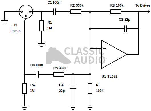
Figure 10. Balanced line receiver for VU meter drivers
Figure 10 details a suitable balanced line receiver for the Figure 7 and 9 circuitry that will not only ensure accurate reading of floating or non-differential balanced lines but will also give handsome rejection of common mode noise (although whether common mode noise will be visible on the meter movement is rather debatable for most high quality setups). The balanced receiver shown in Figure 8 is designed specifically for use with level metering circuits such as Figures 7 and 9 and is therefore not intended to be a high quality low noise balanced input. Rather it is optimised to present a high impedance to the line of greater than 200kΩ and to bring a +4dBu professional balanced line level of 1.228V RMS down to a more workable 286mV RMS that the meter drive will want to see. It is possible to put this level into the meter without any prior attenuation, but calibration may be a little more fiddly towards the end of the trimmer potentiometer's range where higher rotational accuracy will be required of the hand on the end of the adjusting screwdriver. The level drop also makes running the receiver off lower supply rails of less than ±15V without the possibility of clipping more feasible. With input and feedback resistor values in the hundreds of kilo ohms so as to keep the loading on the line low enough that additional equipment might be connected to it, the receiver's output is rather noisy at -100.2dBV, made even worse by the fact that the differential gain is -12.7dB to yield a shocking EIN of -87.5dBV, but this is still at least an order of magnitude lower than what will be visible on the meter movement.
When feeding the Figure 7 driver circuit from Figure 10, rather than directly from an unbalanced line, it is possible to short out and omit C1 and R3 from Figure 7, as Figure 8 already performs RF rejection and DC decoupling, making these redundant functions in the meter drive circuitry. Figure 7 and 8 may be built from a single TL072 or TL084 op-amp to form a complete meter drive and balanced receiver with a single IC. Stereo versions may also be built with the TL074 and TL084 ICs. It is the opinion of the author that it is well worth the additional complexity of building Figure 8 for a balanced line, as opposed to just optimistically connecting Figure 7 to one side of the line. If the balanced receiver is to drive any circuitry in the audio through path, then Figure 8 is quite unsuitable and a high quality balanced receiver must be used unless very poor noise performance and probably poor linearity is acceptable.
Split supply for improved circuit
A complaint intermittently heard when split supply rails are included in a design, is that split supplies are awkward to build, using twice as many components and being unduly complex compared a single supply rail design. It is certainly true that the supply circuit itself is much simpler, maybe using near half as many components, but the additional complexity starts to rack up very quickly in the biasing networks required in the audio path. It is simply not possible to reduce the component count by using a single supply unless the audio path is very simple; a single stage, single channel circuit topology. Revisiting Figures 7 and 8, it becomes clear that an additional 5 components are necessary to make it work.
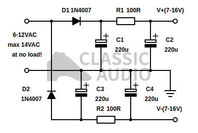
Figure 11. Simple split supply for Figures 7 and 9
Figure 11 demonstrates how a practical split supply circuit, that satisfies the requirements of the Figures 7 and 9 can be brought to fruition with little effort and only 8 components that most constructors will already have lying around. A simple half-wave rectifier to the positive and negative rails, via D1 and D2 respectively, derives a positive and negative voltage with respect to ground, which is then smoothed by reservoir capacitors C2 and C3. Additional RC smoothing is effected through R1 and R2, in partnership with C2 and C4 respectively. No regulation is required, and a ripple voltage of less than 100mV on the outputs with a loading from the Figure 7 circuit of up to 10mA was measured. Considering that the TL072 affords upwards of 70dB, typically 100dB, of power supply rail rejection, this is absolutely nothing to worry about. Regulating the supply as it is would prevent it from developing sufficient output voltage with lower voltage AC sources, such as 6.3V valve heater windings, for the Figure 7 circuit to work with due to the drop-out voltage. Additional quiescent current draw, and safety margin over drop-out voltage, inherent to linear regulator arrangements would put further unnecessary limitations on the flexibility of the power supply.
The smoothing resistors only need to be quarter-watt types, and the capacitors should be rated for twice the AC input voltage to secure longevity. The AC source can be a small plug-in wall wart, or a small (<5VA) transformer if the constructor is comfortable and competent in AC wiring. If not, then the wall-wart type must be used as it will most certainly be double insulated. The no-load AC voltage should be above 6V RMS, but must not exceed 14V RMS at no load, as this will result in an output voltage possibly high enough to damage the op-amp. Most transformers output voltages are specified at full load, and extra windings are usually added on the secondary to overcome the voltage drop at full load due to winding resistance. With no load present the output voltage may be up to 40% higher than the rated voltage (a rated 12V transformer might put out over 15V!), especially with smaller, less efficient transformers. It is a good idea to measure the no-load voltage of the wall-wart supply or transformer with a multimeter to make sure it does not exceed 14V before bringing it into a potentially frustrating service. If the constructor has free choice of transformer secondary voltage, as opposed to using a pre-existing one already in his possession, the author recommends 9VAC as a safe bet.
A 6.3V heater winding, found inside most valve amplifiers, as previously alluded to, will also comfortably feed the split supply, making the circuit especially useful to the constructor with a penchant for these devices. The winding must not be connected to the chassis ground by any other route than the ground node in view at the output end of Figure 11, or ground loop trouble may be encountered.
LED back-lights are now quite commonly used for illuminating VU meters made today, being a good deal less efficient than their rapidly disappearing incandescent counterparts, especially if a series connection is made between the back-lights of two or more meters. If LED back-lights are present, they may also be powered by the supply in Figure 11, in series with a suitable current limiting resistor. The back-light must be powered across both of the the ± output rails, as opposed to between one rail and the circuit ground, to make certain that no DC current can flow across the transformer winding, which it will if one half-wave rectifier section is loaded with a higher current than another. If a net DC current flows through the winding of any mains transformer, it may suffer, these parts being ill-disposed to tolerate unipolar DC flowing through their windings.
Calculating the LED current limiting resistor, using a a typical 6.3V AC winding, freely found inside the viscera of most valve equipment, resulting in some ±8V available at the power supply outputs with no load. Take, then for instance two meters, with white back-lights of a forward voltage of 3.4V each, with a rated current of 20mA, giving a total of 7.2V when connected in series are to be used with a forward current of 12mA. The author is not well taken through experience to trust the advertised forward current, and prefers to adopt a safer refuge below 70% of this parameter. Having subtracted the 7.2V drop of the LEDs from the combined voltage of 16V between each supply rail to yield a remaining 8.8V to be dissipated at a current of 12mA, a quick R=V/I calculation reveals a series resistance of 733Ω is required in series with the two LEDs to complete the line up. However, the two smoothing resistors must also be subtracted from this value as they are also in series with the LED string. Subtracting the total series resistance of R1 and R2, 200Ω, from the previous value gives 533Ω. This, after subtraction of a further 50Ω to compensate for the additional loading of the VU drive circuit itself, winding resistance, and various other factors that conspire to reduce overall output voltage in unregulated supplies as loading increases, produces 483Ω. Thus, a 470Ω (E12 value) series resistance should be put into use.
Troubleshooting meter damping
Some constructors who have built the circuits have got in touch to report issues with meter movement damping where the meter exhibits gross overshoot and ringing with normal programme material. In all cases, this has been caused by using low quality meter movements of the kind typically found in the sub $5 price range on direct-from-China retailers on eBay, Aliexpress, or Alibaba. While the author recommends using a higher quality meter movement that may cost only a little more, such as those available from Flash Star, it is still possible to use these parts by increasing the value of the meter damping capacitor, shown as 22µF throughout of the course of the article, most often by a factor of 10. Doing so does of course make the meter a little more sluggish, much like those seen on lower quality equipment from the 1970s, but is a good deal better than having a meter than shoots off the scale in both directions given only the gentlest tickling. In one case, a capacitance of 440µF was required to critically damp the movement; a sure sign that the moving mass was at the bottom of the manufacturers list of priorities.
It goes without saying that if the time to construct a high quality driver circuit such as those that have been detailed above is going to be taken, then it is well worth spending what may only be the price of a cup of tea in any high street café extra in obtaining a better quality meter movement. As is always the case any audio circuit can only be as good as the transducer that it is connected to, and metering is no exception.
Conclusion
This article has ended up reading significantly longer than the original, most of it due to additional information that readers who got in contact felt was necessary for them to be made aware of to complete their builds and make suitable power supplies and line interfacing circuitry for said builds. Hopefully the information in this article will be of better use to the future constructor, as a consequence of this endless updating.
Many of the circuits listed on the web have numerous flaws including distorted input current, distorted ground current without provision for separate grounding, poor sensitivity, inaccurate and unresponsive half-wave operation and many other deficiencies. While this article contains a total of 5 different driving circuits for VU meters, the author considers only Figures 7, 8 and 9 to be worth building in comparison to the other examples. The greatly increased low-end sensitivity of the improved circuitry described here is readily apparent in use and is quite a pleasant surprise to anyone who is used to the less sensitive contemporaries out there. If the meter scale shows an incorrect reading in the compressed lower range of meters designed to compensate for sensitivity limitations, then the movement can be aligned further to the left. This is most often done by adjusting a screw below the glass window anti-clockwise.
Sometimes using a passive meter such as the ANSI type will ultimately be simpler to implement than any active circuitry, so long as the precautions highlighted are taken. It all boils down to cost, space, and simplicity. However, considering the cost of the meter in comparison to the driving circuitry, which is simple enough to take up very little room and can easily be powered from the range of supply rails present in most audio equipment, it is the sentiment of the author that going the extra mile with some of the active circuitry shown in this article is well worth it.
If you have any questions or comments relating to this article, then feel free to contact the author.